Modified 05/02/2019
|
This schematic and source code are intended
for demonstration purposes only. They are offered "as-is". Use at your
own risk.
Code and circuits (and more) are here. |
Introduction
This project is for the hobbiest who wants to build a measurement and display unit for an Awana Grand Prix® track (also known as a Pinewood Derby track.)
The racetrack for which I designed this unit is a 4-car track.
A car is approximately seven inches long, is released by a gate at the starting line,
rolls down the ramp by gravity, and crosses the finish line in approximately five
seconds. This was designed for Christ Memorial Church, Williston, Vermont, USA.
Click on photo to display full size version.
This circuit is contained in three places: in the controller/display box, in the finish line "bridge" unit, and at the start gate. The power supply, the controller/display box, and the start gate switch/servo each connect to the track finish line "bridge."
The controller box also has a USB jack for connection to a computer with appropriate software. Recommended and tested race management software is "GrandPrix Race Manager" from GrandPrix Software Central. This software is well-written by Randy Lisano, highly configurable (easily customized to work with this track controller) and produces a full-screen image that is very suitable for use with a video projector.
Click on photo to display full size version.
C code
Schematic
Features
Timing is initiated either by pressing the push button or by computer control. The controller waits for one or more cars to cross the finish line and displays the order of finish as well as elapsed timing information.
Specifications
- Control modes:Manual (push button) or Automatic (computer)
- Power:12V
- Serial:9600-8-N-1
Screens
Power on message (insert your own here.)
|
Lane masking screen, after which instructions appear for masking one or more lanes. This allows defective lanes to be ignored. Lane masking setup may also be done remotely from software.
|
Ready screen. To start the race timer, either press the push button or start remotely.
|
Lane color and times appear in order of finish.
|
If one or more lanes finish with the same same, TIE! is inserted on the display.
|
If one or more lanes are masked, MASKED appears in the bottom row(s).
|
The maximum elapsed time is 9.999 seconds. Any car that does not finish will time out at the maximum. Any lane that is masked appears as 9.999 seconds.
When the button is pressed, the controller will not start timing if any phototransistor is blocked. A screen message will be displayed accordingly.
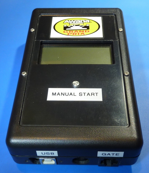
Manual operation
There is only one control...the "Manual Start" push button.
Lane masking, if desired, is configured immediately after power up
by pressing the button when prompted for lane masking and following
the ensuing prompts. Unmasking is done by powering off and on, or by commands from
remote software. Race timing is started by software or by pressing the button at the Ready prompt.
Remote operation (computer controlled)
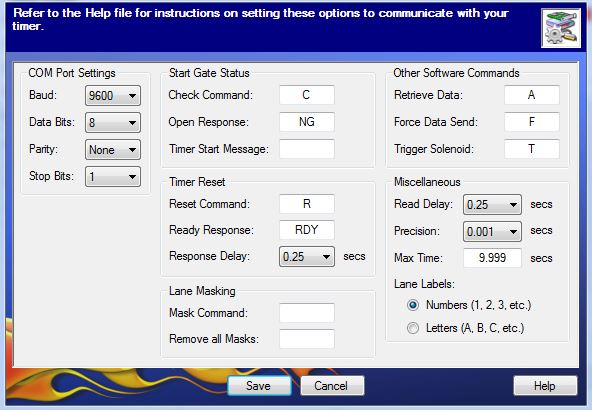
The computer may send commands to the controller/display unit and expect responses. If using Race Manager V15 software (and maybe a few previous versions,) these commands are entered into the custom setup screen to define what the computer will send via it's serial port in each instance, and what it will expect to receive back from the controller box. These uppercase commands (NOT followed by CR/LF) are:
- "R" - reset. This resets the controller. The controller sends "RDY" as a response.
- "F" - force elapsed times to be returned immediately for any lane that has finished before race is completed. Unfinished lanes are returned as 9.999 seconds.
- "A" - return elapsed times again (if needed.) Normally the controller sends the race results after all four lanes are finished, or time out, or are otherwise accounted for (when one or more lanes are masked.)
- "C" - check track status. Depending on what checks were selected at compile time, either finish line phototransistors or both finish phototransistors and start gate status are checked. If a finish line phototransistor is blocked and/or the start gates is down, the controller sends "NG" to the computer; otherwise "GD" is returned.
- "T" - trigger the start gate to drop (same as push button) and start the timer
- "M1" - (or M2, M3, M4) mask an individual lane.
- "X" - unmask all lanes.
The controller/display unit returns elapsed times to the computer with the format (from the same race as the example above):
1 5.381 2 6.101 3 5.344 4 5.720
Any lane that doesn't finish times out at 9.999 seconds. Any lane that is masked appears as 9.999 seconds.
If you are using one of the newer versions of Grand Prix Race Manager by GrandPrix Software Central, the following photos illustrate how the commands above are used in the configuration screens.
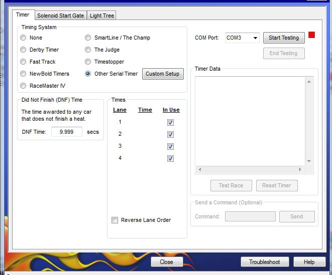
Click on photo to display full size version.
Click on photo to display full size version.
Diagnostics mode
Diagnostics mode is entered by holding down the push button while powering up. Live start gate position (up or down) and finish line phototransistor status is displayed until the button is released, after which the controller resets and resumes normal operation.
The example below shows the start gate in the up (ready) position, and that someone is testing the track by blocking the Red, Blue, and Yellow lane phototransistors, but not the Green phototransistor.
|
Technical Reference
HARDWARE - Controller
- A standard Ethernet cable was used to connect the controller/display
unit to the finish line "bridge" unit.
Click on photo to display full size version.
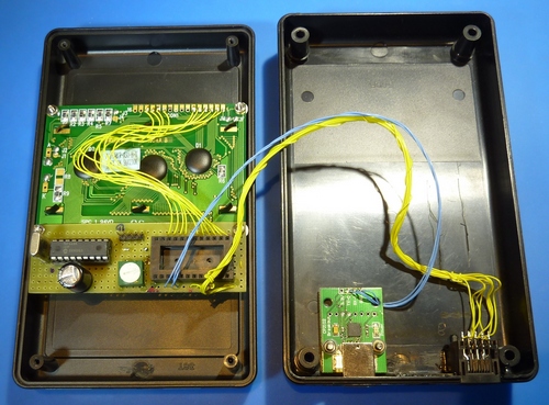
- The other connector in the controller box is a USB connector.
The connector is integral to the UART-to-USB "breakout board" which
carries a UART-to-USB "bridge" chip. A bridge chip accepts 5V serial
Rx and Tx signals and converts them to a USB "virtual COM port" at the 9600 baud rate
being transmitted by the PIC. When plugged in to the computer, after USB enumeration
a COM port will be created, usually with a number a lot higher than the COM3 and
COM4 from the early days. "COM23" is an example.
The board in my unit happens to be a breakout board for the Silicon Labs CP2102
bridge chip. Other bridge chip manufacturers are FTDI, Cypress Semiconductors, and Microchip.
Since these chips almost always surface mount chips, buying a "breakout board" from a
distributor such as Digikey or SparkFun makes it easy to build in to a project such as this one.
The key elements to understand when using a UART-to-USB bridge are;
- You want to use it in "bus powered" mode which means that the chip is powered with 5V from the USB bus, not the controller. That way it doesn't confuse the computer or software by dropping the USB connection when you power down the controller.
- You want to set its interface voltage to 5V to match the signal levels at the PIC.
- A current (March 2017) example of a UART-to-USB breakout board using the Cypress CY7C65213 chip may be purchased from SparkFun Electronics, part number BOB-13830, $12.95USD. The same thing is available from Digikey, part number 1568-1504-ND, same price.
- Remember that USB devices require USB drivers in the computer. If they aren't built in to the operating system they can be obtained from the chip manufacturer.
- The four-pin header between the two dip modules is the ICSP port
by which the PIC can be programmed in-circuit. All that is needed is
RB6 (clock), RB7 (data), and MCLR/RA5 (Vpp). The 16F648 in particular,
needs the LVP pin (RB4, pin 10) pulled down to keep it out of low-voltage
- MCLR is not active in this application because "NOMCLR" is in the configuration word. The only reason MCLR (RA5) has a pullup resistor is because RA5 is also used as the manual push button input.
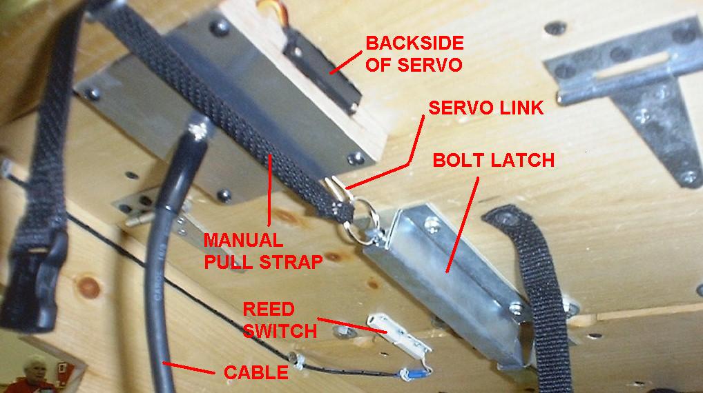
HARDWARE - Start gate actuator and switch
- The actuator for the start gate is a standard three-wire radio-control servo unit. These have
enough torque to pull a small cable that pulls a (lightly loaded) bolt latch or similar. The
controller box code rotates the servo approximately 110 degrees. The connection between servo and latch
must be such that either the servo or the manual pull string can actuate the latch without damagine the servo.
Click on photo to display full size version.
- The start gate switch is used to check if the gate is up or down. The switch is closed when the start gate is up. The white switch in the photo is a reed switch and magnet.
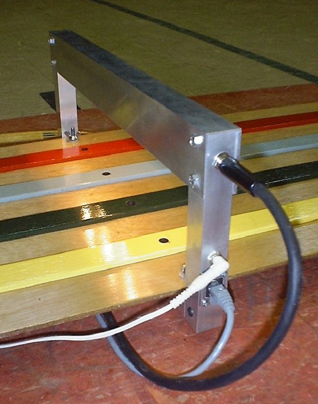
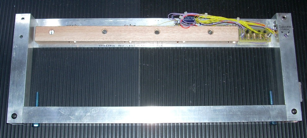
HARDWARE - Finish line "Bridge"
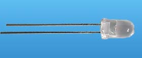
- IR LEDs are mounted above each track lane an a "bridge" assembly to
illuminate IR phototransistors in the base of the bridge which is under the track.
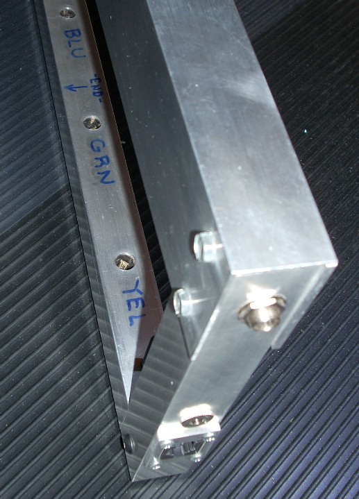
The end of the track is inserted through this bridge and the vertical
bolts and wingnuts secure the bridge to the track. There are four holes
in the track that align with the phototransistors in the lanes.
When a car breaks the
light beam the microprocessor registers the finish on that track.
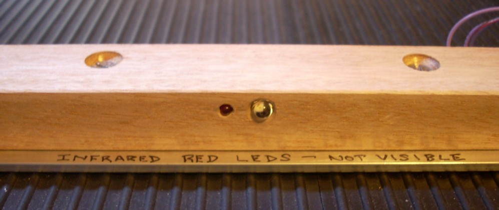
Click on photo to display full size version. - The IR LEDs are wired in series with a second visible red LED to show that the current is flowing
(and to "reassure" people that there is a light beam there even though the IR LEDs look dead.)
- The reason for the 1K resistor in series with the signal wire (yellow) on the servo is to limit possible current from the 5V at the tip of the 1/4" plug when it's first inserted into the jack and slides past the sleeve ring.
- The photo circuitry will respond to the 60/50Hz line frequency of fluorescent lamps at certain brightness levels so it's a good idea to shield or baffle the IR phototransistors so that the only light reaching the phototransistor is from the DC lamp directly above the track. This may be done by housing each phototransistor in a relatively narrow, cylindrical sleeve (such as shrink tubing). If the length is three or four times the diameter of the sleeve, light coming in at an angle will be suitably blocked.
- Any type of photo-sensing circuitry may be employed; all that is necessary to trigger the microprocessor is an active-low. FET's make a good high-gain single-stage solution.
- Care must be taken to ensure
that no debris falls into or over the phototransistor and blocks the light.
While this rarely occurs during the course of a race, it will be sensed by the
controller box so that it can be rectified before continuing:
- If the manual push button is used to start the race, any blocked phototransistor will result in a message on the display. The blocked phototransistor must be cleared before the controller box will start timing a race.
- If the computer software is used to start the race, the "start gate" check that is sent to the controller box will result in the "NG" error message if any phototransistor is blocked.
- This unit is shown without it's "L-shaped" cover over the upper section.
This nicely-built, robust bridge was constructed by Bruce Singer.
Click on photo to display full size version.
SOFTWARE
- Start gate status and finish line blocked phototransistors may be checked. Either no checks, or finish line only, or finish line and start line may be selected at compile time.
- If the start gate actuator (R/C servo) is not used, the code may be modified to use the start switch to trigger timing.
- Accurate race timing is accomplished by a one-millisecond interrupt. It's accuray may be adjusted in the timer interrupt code. The "set_rtcc()" instruction reloads the clock/counter at the beginning of each interrupt cycle to prestart the timer count at a suitable value that results in a precise 1mS interrupt rate. However, absolute accuracy is not really important in this application. Relative accuracy is quite fine. What is important is that the four lanes are checked simulaneously, that is, no lane has any priority over any other.
- The timing resolution of this design is 1mS. If two cars finish in the same 1mS time window, they will show a tie. At this resolution you will rarely see a tie, (which shows how inaccurate finish results are when done purely by eye, where ties occur often.)