Modified 05/20/09
This schematic and source code areintended for demonstration purposes only.
They are offered "as-is". Use at your own risk.
Code and circuits (and more) are here.
Introduction
This circuit is liquid level detection and communication system for conductive (and non-flammable) liquids that utilizes a variant of Raytheon's proprietary marine-oriented Seatalk® bus. It was designed for marine applications (fresh water tanks and waste holding tanks. The former is unpleasant when empty; the latter is unpleasant when full!)
Features
Up to four detection units, all in talker-mode, can transmit onto the bus. The receiver displays each of the liquid levels as a percentage.
Specifications
- Transmitter: Two tank number bits, five detection bits (20, 40, 60, 80, 100%)
10-second averaging. The transmitter board was fabricated using the ExpressPCB
"miniboard" service.
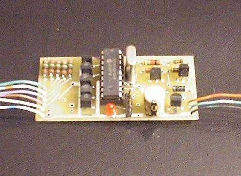
Click on photo to display full size version.
This version uses surface mount components.
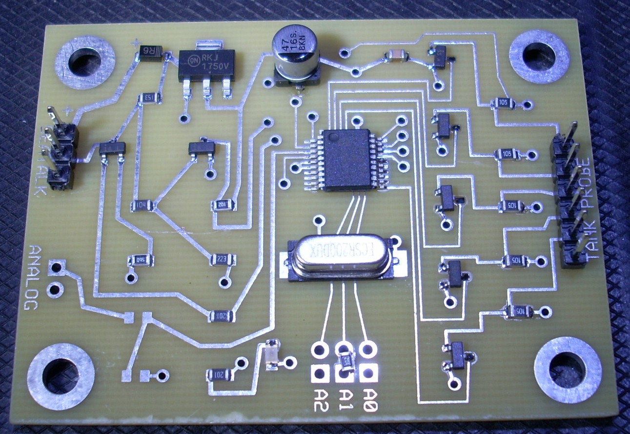
Click on photo to display full size version.
This is a probe assembly.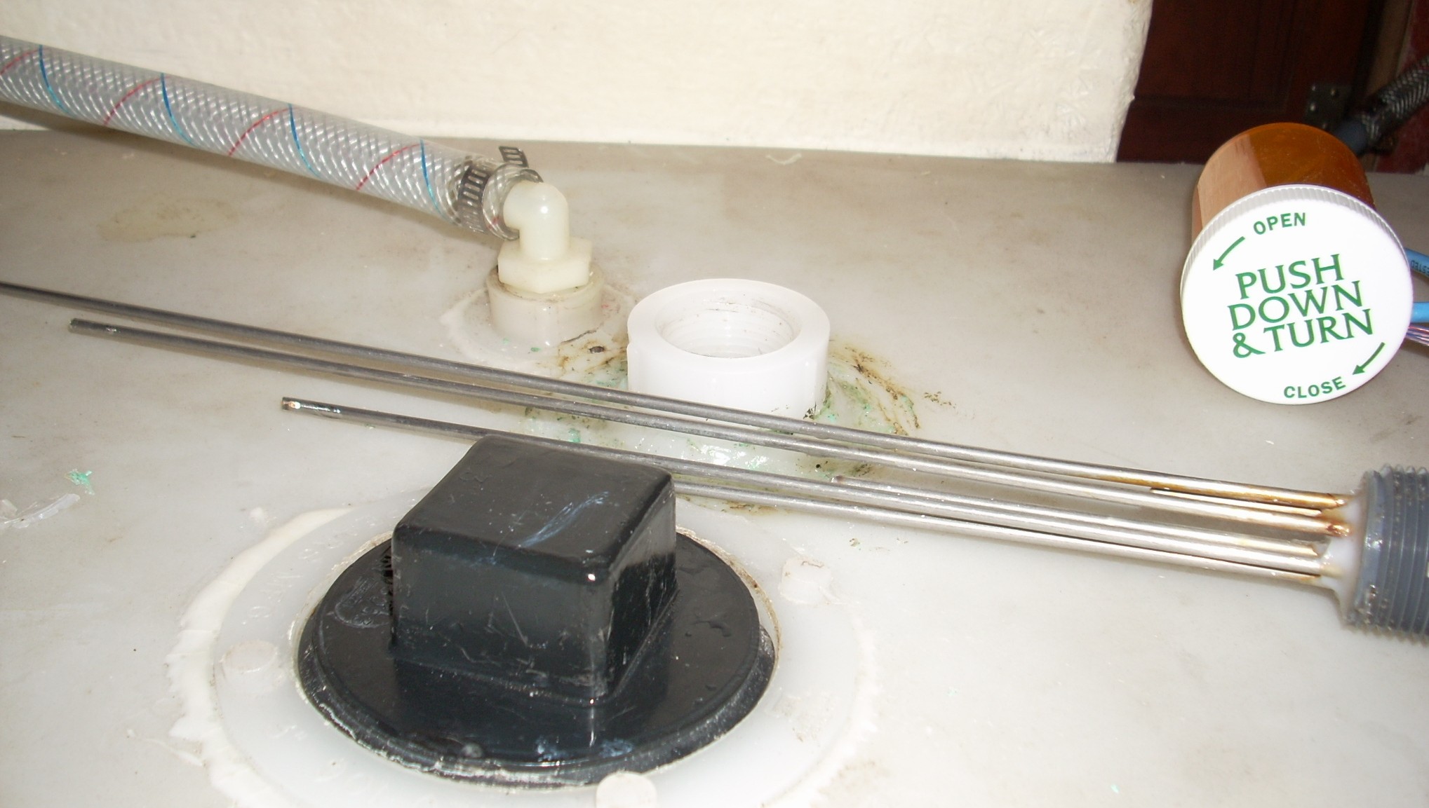
Click on photo to display full size version.
- Receiver: Pulls data line up (presently has no timeout for loss of data signal)
- Power: 8-16VDC at 5mA
- Data: protocol (as best it's known) is 12V, 4800 baud, 1 start bit, 8 data bits, 1 cmd bit, 1 stop bit bit, all are talkers)
Operation
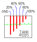
Transmitter sense rods are arranged in the tank(s) as illustrated. It doesn't matter which rod goes to which input, except the ground must be connected to the lowest rod. This is because the software simply adds 20% for each rod that is in the liquid. Order doesn't matter.
The receiver and one or more transmitters are connected to the +12, Data, and Shield wires of the bus. Hot plugging is OK.
Pins A0 and A1 are set low or high to define the tank number of a particular transmitter. Connect to ground to make low; leave open to set high.
                      A1   A0
                   |----------
     Tranmitter 1  |  1    1
     Tranmitter 2  |  1    0
     Tranmitter 3  |  0    1
     Tranmitter 4  |  0    0
The transmitters have an adjustable holdoff period based on the two bit tank number assigned to each transmitter. Thereafter, each transmitter broadcasts it's number and level once per second.
The receiver listens for data messages and after validation, displays the level value broadcast by each of the transmitters. In the particular design, only the first three of the four tank numbers are used and displayed.
|
Technical Reference
BUS HARDWARE
- Transmitter transistors Q1 and Q2 can be any suitable small-signal NPN type that can handle at least 12V. Q1 is the transmitter; Q2 is the receiver. Both invert the sense of the software, meaning that when the software sets RA0 (the Tx pin) to HIGH, transistor Q1 pulls the data bus to 0V. And, when +12V is received by transistor Q2, the transistor pulls RA1 (the Rx pin) low. Pin RA1 should always follow RA0; if it doesn't a bus collision is assumed by the software. Refer to Bus Software notes, below.
- R2 (5K) in the receiver pulls the entire data line up for any number of transmitters, thus the weak R1 pullup may be omitted in each transmitter. However, if testing a transmitter that is not connected to the bus, R1 will be necessary if you want to see the broadcast 12V data levels on an oscilloscope. (I noticed that certain Raytheon marine instruments that were connected to the same bus as my three level transmitters had trouble pulling the bus low if each level transmitter had the R1 pullup installed. I removed R1 in every level transmitter.)
- You may need to install a 22K resistor from Q2-base to ground. This will make it possible to sense marine instruments on the bus that are (for some reason) not pulling the bus low enough during their transmitted message.
- If you are testing the transmitter microprocessor alone in a stand-alone test socket without the peripheral Q1/Q2 circuitry, be sure to connect pin 18 (the Rx monitor) to pin 17 (Tx). Otherwise the code will think that a data collision occured (because Rx won't match Tx bit-for-bit), and will immediately stop the message transmission, and will attempt to retransmit the entire message continuously, in which case all you will observe on an oscilloscope will be a continuous stream of start pulses.
- To observe the messages on the bus with a PC terminal emulator such as Procomm or Hyperterm, connect RS-232 pin 2 (assuming a 9-pin RS232 connector) directly to the Rx pin on the PIC. Connect RS-232 pin 5 to ground. Remember to include the parity bit in the setup of the terminal emulator. Another DOS-based display program is found on Thomas Knauf's web site called SEAMON1.EXE.
- The reason for the Q2 inverter stage in the receiver (instead of the INVERT keyword on the "#use rs232" statement in the receiver code) is because the bus is running 12V data. I suppose a series current limiting resistor could be used instead of the transistor, letting the PICs ESD diode to Vdd clamp the incoming voltage at 5.7V, but that just doesn't seem like a clean solution.
MISCELLANEOUS HARDWARE
- Any 5V regulator may be used.
- Diode D1 is simply for reverse polarity protection and may be omitted if reverse polarity won't happen.
- The transmitter Port B bits have external pull-up resistors activated in the software code. Thus, the drains of the five FETs, as well as the two tank number bits, do not need external pullup resistors.
- The liquid must be conductive and must not be flammable. The 2N7000 FETs provide a high impedance input and allow for wide variations in liquid conductivity.
- Fouling of the tank rods will result in inaccurate readings. This may be a particular issue in a waste tank where conductive solids could stick to the rods. This would have to be mechanically prevented.
- There are five sense rods that correspond to 20%, 40%, 60%, 80%, and 100% capacity. These rods extend downward into the liquid to depths that correspond to those percentages. A sixth rod (ground) extends into the liquid below the other five rods.
- If the tank is not cubical in shape (tanks having a triangular cross section are often found on boats) the rods are extended to adjusted depths so that the five percentages are still correct. It's advisable to locate the rods in such a manner to maintain level accuracy despite rolling motion of the tanks (if in a boat.) Often that will be in the lateral center of the tank.
- Galvanic corrosion of the stainless steel sense rods due to DC sense current is not expected to be a problem. Assuming the liquid is water, the DC resistance in a test setup of stainless steel rods exhibited something like 100K ohms. That, plus the 1M resistor results in a current of approximately 5uA, and that current is applied to each sense rod for only 2.1mS, and then only once per second. The ground rod would return the total of the five sense rod currents, or 25uA at the same period and frequency. Thus, corrosion is not expected to be an issue.
BUS SOFTWARE
- Data messages are broadcast in the form: FE 01 0x yy where
- hex FE is the message ID (in this application)
- hex 01 is the number of bytes in the message beyond the mandatory three bytes
- hex 0x contains the tank number (00, 01, 02, or 03)
- hex yy contains the percentage (0 thru 100)
- A message is sent at essentially 4800-9-P-1, where the parity bit is really a command bit that is set to +12V to define the first byte of a message; 0V in the remaining bytes. If messages require more than three bytes (as in this application) any additional bytes follow and the second byte is set to the count of the additional bytes beyond the mandatory three. This application requires four, thus the second byte is set to 01.
- The interesting thing about the protocol is that it is a serial data protocol operating at 4800 baud in which no marine instrument on the bus has an "address" and there is no master/slave or talker/listener relationship. They are all considered talkers. A talker simply listens to the bus for 5mS to ensure it's idle then transmits the three or more bytes in the message. The key element in the protocol is collision detection. Each talker monitors it's own transmission to ensure that no other talker corrupts the message during transmission. If a collision occurs, both talkers retransmit again after some period of time, sooner for the higher priority devices. Since talkers listen for longer than one character time (2.28mS which is 11 bits x 208uS) prior to transmission, the only time a collision might occur is if both talkers happen to be listening at the exact same time and then start transmitting, and statistically that is a low probability because Raytheon marine instruments typically broadcast their messages (such as depth, knots, temperature, etc.) every second or two (and lower priority messages are sent even less often.) Thus, there is plenty of room in which to successfully insert immediate (high priority) messages from devices such as a remote control.
- The hardware UART in the 16F628 could have been used, but this code was written so that it could be embedded in the GPS Repeater (on this website) whose UART pins are already occupied with other data. Thus, special provisions had to be made in this non-interrupt-based software, such as timeouts if no start bit is received in a reasonable period of time.
- The SendBit procedure is tuned code such that bit times are as close to 208uS as possible (4800 baud.) An entire four-byte message should take 9mS from the falling edge of the first start bit to the rising edge of the last stop bit. That stop bit itself takes 208uS more, for a total message time of 9.2mS. Future versions may make use of the timer, periodically checking it for timeout while monitoring the transmitted bit (more often than the present code does) to ensure no data collisions occur.
- A good reference is Thomas Knauf's web site, part of which is listed in the source code comments.
MISCELLANEOUS SOFTWARE
- If the liquid height is somewhere between two rods and if there is any motion of the liquid, there may be times when the upper rod will sense the liquid and other times when only the lower rod will sense the liquid. The levels are read at one-second intervals and averaged over ten seconds. Thus, level readings other than 20%, 40%, 60%, 80%, and 100% will sometimes be transmitted.
CORRECTIONS OR UPDATES
- v1.0 - first release