PIC PROGRAMMER
Modified 06/05/12
This schematic is intended for demonstration purposes only.
It is offered "as-is". Use at your own risk.
More code and circuits are here.
Introduction
The "U2 Programmer" is unit is a very nice PIC programmer developed by microEngineering Labs, Inc. It has a USB connector and a 10-pin programming connector. The unit is powered from the USB port. All timing and programming is controlled by an on-board PIC microcontroller. The programmer's firmware may be upgraded from the PC. Commands and data are received from the PC at high rates that never leave it starved for data. It will program a PIC as fast as Microchip specifications allow. Because it's based on a PIC it can drive up to 25mA to help overcome loading conditions associated with the RB6, RB7, and MCLR on the in-circuit-programming-port (ICSP) of the PIC being flashed. The microEngineering U2 Programmer has proved to be a robust programming platform for my projects.

USB programmer photo sourced at Melabs web site.
My hardware implementation
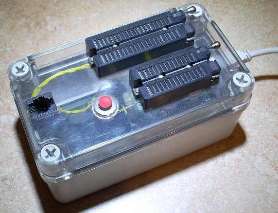
Although melabs sells a small box for the U2 Programmer I installed it in my own plastic box with two ZIF sockets and a reset pushbutton.
microEngineering Labs advises against powering application hardware from their on-board 5V regulator, but it appears that the regulator is quite capable of powering a PIC during programming in the stand-alone ZIF socket. Hence my implementation routes the +5VDC to the two ZIF sockets but not to my ICSP connector.
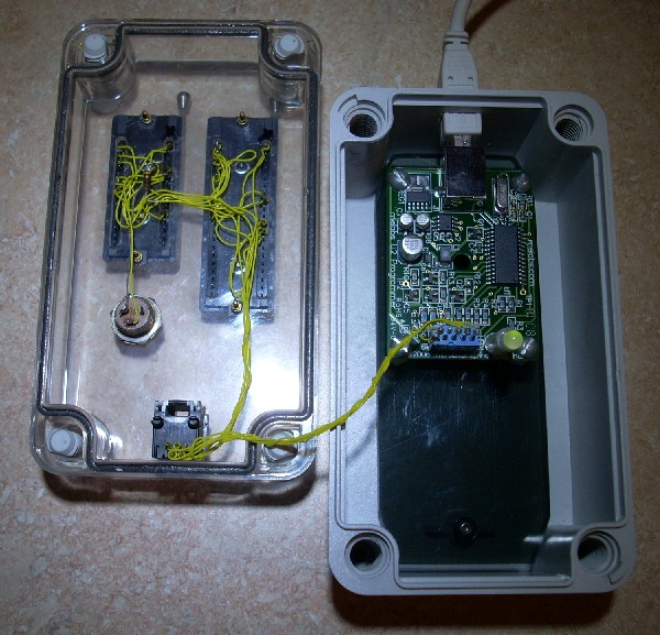
One ZIF socket is for 28 and 40-pin PICs. The other is for 8, 14, and 18-pin PICs. A good alternative to building up a custom box such as mine is to buy one or more of the melabs adapters.
The reset button is intended for when the ICSP cable is connected and when MCLR is enabled in the PIC. It's helpful during project debug when the application doesn't have a reset button of it's own. The 100 ohm resistor prevents a direct short to the programmer's electronics.
The black RJ-12 (telephone) jack is used for cable connection to the ICSP connector on my boards.
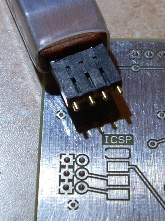
- For thru-hole boards I simply install a 4-pin strip. My cable has
a 4-pin female connector on the end.
- For surface mount boards I built a probe that contains four pogo pins
inserted into a 4-pin 100-mil shell. The pogos contact a pad pattern
on the board. I incorporate a 4-pad pattern into the board layout (below,)
typically on the back side.
- PICs that are powered with a 3.3V supply usually can't be bulk
erased by the PIC programming process unless the supply
voltage is increased to +5V. Since that's normally possible
without damaging other components that are tied
to that supply, a way to handle 3.3V PICs is to power the PIC
through a series diode which will prevent the +5V programming
voltage (pin 1 in the MELABS programmer) from backfeeding
into the rest of the 3.3V supply.
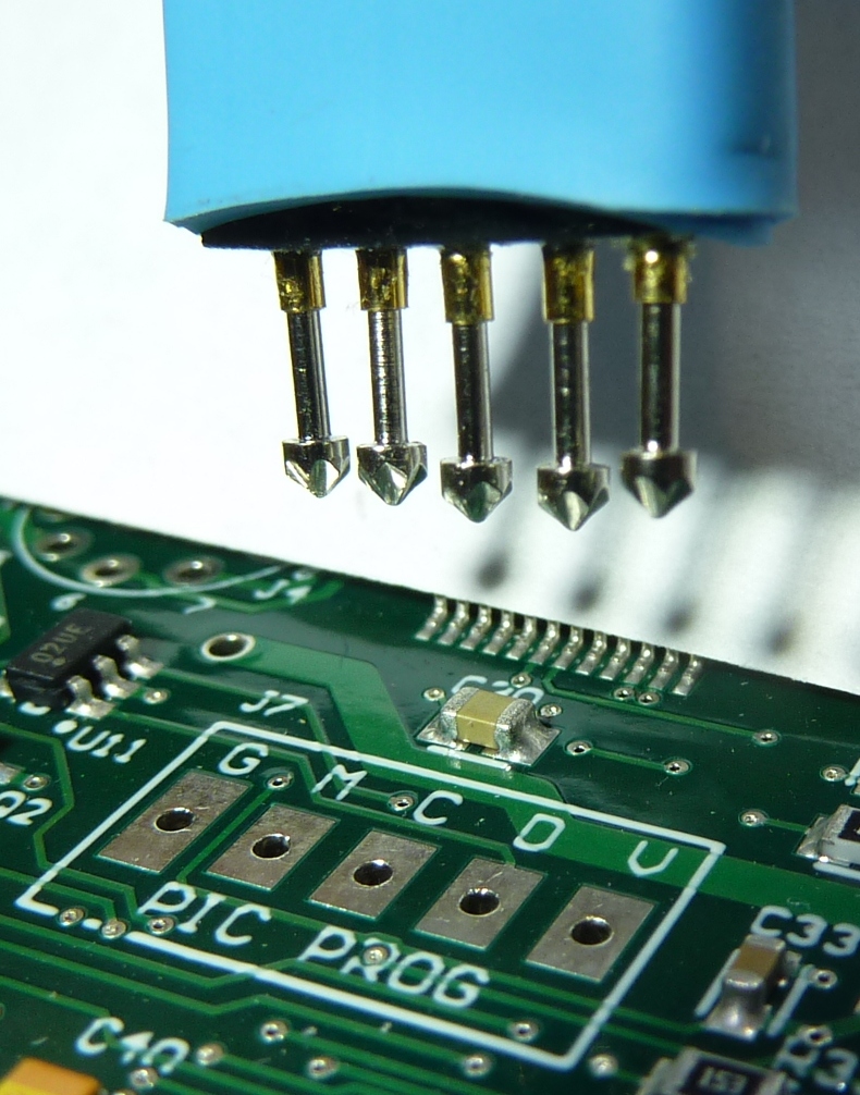
I built a probe that contains five pogo pins inserted
into a 5-pin 100-mil shell. The fifth pogo
brings the +5V programming voltage to the PIC being programmed.
The MELABS programmer is designed to supply +5V to the PIC being
programmed but is not designed to power anything else at the same time.
The pogo pins were obtained from
Adafruit Industries.
Accommodating Low Voltage Programming mode
Certain PIC's such as the 16F628 need to have their PGM pins tied low during programming to ensure that Low Voltage Programming is disabled while programming with the U2 Programmer. The symptom of LVP issues during programming is a message box that pops up stating that there is a "programming error at address xxxx." Since the PGM pin is tri-stated during programming, it's therefore vulnerable to electrical noise. Both on-board ZIF sockets have the PGM pins tied to ground through a 1K resistor for this purpose, illustrated in the following schematic, but if using the ICSP cable to program such parts in the application socket, you need to ensure that the PGM pin will be effectively pulled low. In some applications, you might be able to ground it directly. Other applications might require a 1K or 100K resistor, depending on what the pin is being used for.
Schematic
meLabs Software
The software is well-designed and straightforward. It includes a command line interface so that the software can be invoked directly from the CCS Compiler and other programs.

Photo sourced at Melabs web site.
meLabs Support
Pleasant and kind folks! Reponsive! Fast updates to add new devices! Great support!