| ..................
|
Modified 01/17/2015
Code and circuits (and more) are here.
Introduction
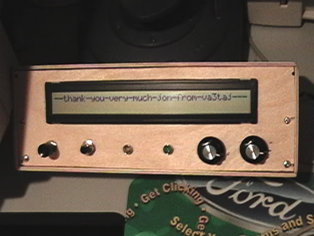
This circuit provides a Morse code-to-text conversion.
Morse code on the speaker of a shortwave receiver is heard by a
microphone and the text-equivalent is displayed on the LCD.
This circuit is not as refined as it could be, and
I haven't gone any further with it. The hardware nicely discriminates
morse tones at the adjusted pitch and ignores tones at any other pitch, but
correct decoding seems to depend on how stable and by-the-rules (dot time vs.
dash time vs. space time) the Morse code is. Although it does correctly display
some operators' code, I suspect the software could use some refining to make it
smarter and more adaptable to a wider spectrum of ham styles. Javier Taboada
successfully made some code modifications, incorporated a longer display,
and did a first-rate packaging job.
Features
- After reset is pressed, the microprocessor listens to the next 10 code tones
to "learn" the dot/dash timing. "CALIBRATING" is displayed during this time.
- Thereafter, incoming code is interpreted and the characters are displayed
on the scrolling LCD display.
Instructions
The pitch of the code must match the center frequency of the 567 tone
decoder. When adjusted properly, the LED will light when the tones are heard.
There are two ways to accomplish adjustment...
- For unmodulated carriers, tune your receiver's BFO to the correct pitch.
- For modulated carriers, tune PITCH (R2) to bring in the signal.
The volume and signal-to-noise ratio must be reasonable, but are not critical.
The 567 does a good job weeding out adjacent signals, noise, etc.
To recalibrate at any time, press RESET.
Tech Reference
HARDWARE
- The microphone is a standard two-terminal electret condenser type. These are
commonly found in computers, telephones, and electronics suppliers.
- The LF351 opamp can be any reasonable opamp. The gain is approximately 80.
Set GAIN (R1) so as to provide 1 volt of signal to the 567. (Although the 567
will respond to much lower input voltages, it's bandwidth will be reduced.)
Overall gain does not seem critical; the volume of the shortwave receiver may be
varied to suit. Thus, the R1 pot could be replaced with a fixed resistor of a
suitable value.
- The tone decoder is any 567 variant (The Exar XR2211 is only one of several
available. The 567 is close to obsolete if not already.) The center frequency
is adjustable from 500-5000Hz. 1000Hz seems to be a good setting. There are
two filter capacitors...
- C2 is a low pass filter that has an effect on the 100Hz bandwidth (higher C2
means lower bandwidth.) If the bandwidth seems to low to accommodate unstable
BFO's, you might want to reduce the value of C2.
- C3 is an output filter that eliminates spurious out-of-band signals. It's
typically greater than C2. If too low, it allows spurious noise; if too high,
slows down the output response time and some the silence between dots and dashes
will not be recognized. The value seems to be somewhat critical.
- The LCD, as connected in the schematic, is a standard 2x16 display initialized
for 4-wire bus to save microcontroller I/O pins. The code includes commented-out
lines that send characters to a 9600-baud terminal instead of an LCD display, if
desired. If desired, a 2x40 display may be used by connecting 16F84 pin 2 (RA3)
to +5V instead of ground.
- The 16F84 has a test output (pin 1) that drives an LED. It should light at
the same time that the 567 LED lights and indicates that the processor has
completed the 10-tone "learn" mode and is presently in "listen" mode. After
calibration, dots/dashes are discriminated by measuring whether they are shorter
or longer than the threshold time determined during calibration.
- The audio preamp section may be eliminated or modified if it is desired to
take the signal directly from a shortwave receiver without the microphone.
|