Modified 04/22/04
This autopilot-related schematic and source code
are intended for demonstration purposes only.
They are offered "as-is". Use at your own risk.
Nothing precludes good seamanship.
Code and circuits (and more) are here.
Introduction
This circuit is a remote control for the Raytheon ST4000+ Autopilot. It communicates via Raytheon's proprietary Seatalk® bus.
Features
The remote control makes 13 commonly used ST4000+ autopilot functions available at a remote location.
My own autopilot control head is located on the bulkhead next to the companionway hatch. Although convenient during a rainstorm because it's accessible while sitting under the dodger, it's not easily accessed when standing behind the wheel without climbing over somebody. Thus, I located the remote at the wheel pedestal. From both locations I can view the control head (heading, cross-track error, etc,) and control it as well.
There are two versions of the remote control. One uses eight discrete pushbutton switches. The other uses a 12-key membrane keypad. There is code and schematic for each. While either version should be self-explanatory, the following applies to the switch version which is the one I have built and used thus far. Shown below is the discrete pushbutton switch version of the remote control.
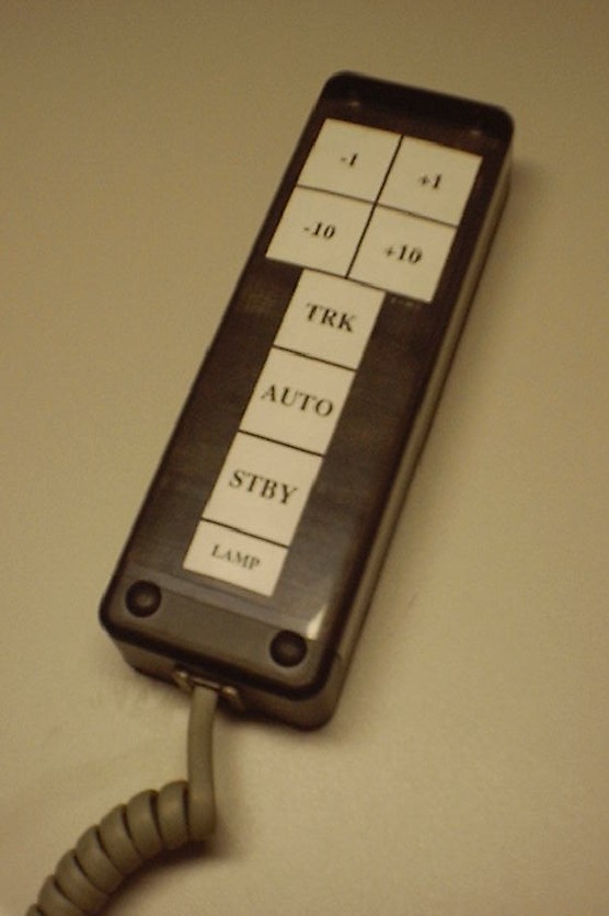
Click on photo to display full size image.
Specifications
- Power: 8-16VDC at 5mA
- Data: Seatalk protocol (as best it's known) 12V, 4800 baud, 1 start bit, 8 data bits, 1 cmd bit, 1 stop bit bit)
Operation
The unit is connected to the +12, Data, and Shield wires of the Seatalk bus. Hot plugging is OK.
When a key is pressed, the piezo alert beeps and the Seatalk message is sent. Certain keys may be held down longer than one second to invoke an alternate function in which case the alert double-beeps and the Seatalk message is sent.
| Key | Function | Alternate function |
|---|---|---|
| AUTO | autopilot follows it's current compass heading | (none) |
| TRACK | autopilot follows GPS route information (cross-track-error.) The autopilot will enter TRACK mode only from AUTO mode. | (none) |
| STANDBY | disengages AUTO or TRACK mode | (none) |
| LAMP/RESP | toggles lamps on and off in any Raymarine instrument on the Seatalk bus. | toggles autopilot between Response Level 1 (automatic deadband) and Response Level 2 (tight deadband.) |
| The functions below are active only in AUTO or TRACK mode. | ||
| +1 | increments heading by 1°. | increments heading by 5°. |
| -1 | decrements heading by 1°. | decrements heading by 5°. |
| +10 | increments heading by 10°. | initiates tack to starboard (just as if +1 and +10 had been pressed simultaneously on the autopilot control head.) |
| -10 | decrements heading by 10°. | initiates tack to port (just as if -1 and -10 had been pressed simultaneously on the autopilot control head.) |
SETUP MODE...
To set an appropriate pitch for your particular piezo buzzer, you may calibrate the pitch by simultaneously pressing and holding STANDBY and TRACK during power-up. Releasing one of the buttons at a time (while continuing to hold the other) will cause the pitch to increase or decrease. Release all buttons when the desired pitch or when resonance (maximum volume) is reached. Operating at resonance might be particularily important from a volume standpoint if the piezo alert is in a sealed case. The setting is stored in the EEPROM memory and is used thereafter unless it's calibrated again.
Technical Reference
HARDWARE
- The MCLR connection is unnecessary in the 16F628 version because reset and brownout conditions are included internally in the 628.
- Transistors can be any suitable small-signal NPN type that can handle at least 12V. Q1 is the transmitter; Q2 is the receiver. Both invert the sense of the software, meaning that when the software sets RA0 (the Tx pin) to HIGH, transistor Q1 pulls the Seatalk data bus to 0V. And, when +12V is received by transistor Q2, the transistor pulls RA1 (the Rx pin) low. Pin RA1 should always follow RA0; if it doesn't a bus collision is assumed by the software. Refer to the Software notes, below.
- Any 5V regulator may be used.
- Diode D1 is simply for reverse polarity protection and may be omitted if reverse polarity won't happen.
- The eight discrete switches don't have external pull-up resistors because the internal pull-ups are activated in the software code.
- Telephone RJ-11 jacks were used so that a coiled telephone handset cord could be used. Refer to the photo above. Not very waterproof, I'm sure, but OK for my application. Category-5 network cable and RJ-45 connectors can also be used. Genuine Seatalk cable appears to be two conductors plus a shield. Twisted pair conductors probably give equal noise immunity so Category-5 cable is probably OK but seems bulky and somewhat inflexible for this application.
- If you are testing the microprocessor alone in a stand-alone test socket without the peripheral circuitry, be sure to connect pin 18 (the Rx monitor) to pin 17 (Tx). Otherwise the code will think that a data collision occured, immediately stop the message transmission, and will attempt to retransmit the entire message continuously, and all you will observe on an oscilloscope will be a continuous stream of start pulses.
- The piezo alert is simply for keyboard feedback. It may be omitted and the output left open. Most any two-wire piezo unit may be used. The software allows frequency calibration as described in SETUP MODE above.
- R1 (15K) is a weak pullup. Assuming other instruments pull the Seatalk data line up, R1 may be omitted. When not connected to the Seatalk bus, R1 will be necessary if you want to see 12V data levels on an oscilloscope.
- To observe the messages on the Seatalk bus with a PC terminal emulator such as Procomm or Hyperterm, connect RS-232 pin 2 (assuming a 9-pin RS232 connector) directly Rx pin on the PIC. Connect RS-232 pin 5 to ground. Remember to include the parity bit in the setup of the terminal emulator. Another DOS-based display program is found on Thomas Knauf's web site called SEAMON1.EXE (Com1) and SEAMON2.EXE (Com2).
SOFTWARE
- The interesting thing about the Seatalk protocol is that it is a serial data protocol operating at 4800 baud in which no marine instrument on the bus has an "address" and there is no master/slave or talker/listener relationship. They are all considered talkers. A talker simply listens to the bus for 5mS to ensure it's idle then transmits the three or more bytes in the message. The key element in the protocol is collision detection. Each talker monitors it's own transmission to ensure that no other talker corrupts the message during transmission. If a collision occurs, both talkers retransmit again after some period of time, sooner for the higher priority devices. Since talkers listen for longer than one character time (2.28mS which is 11 bits x 208uS) prior to transmission, the only time a collision might occur is if both talkers happen to be listening at the exact same time and then start transmitting, and statistically that is a low probability because Raytheon marine instruments typically broadcast their messages (such as depth, knots, temperature, etc.) every second or two (and lower priority messages are sent even less often.) Thus, there is plenty of room in which to successfully insert immediate (high priority) messages from devices such as a remote control.
- Raymarine has introduced that ST290 series of instruments that utilize the new Seatalk2® bus protocol. Seatalk2 is a CAN-based protocol that is much faster than the original Seatalk protocol. Raytheon indicates on their web site that the "ST290 is compatible with the original SeaTalk data format for seamless integration into Raymarine radars, chartplotters, autopilots and fishfinders." Therefore, my assumption is that this remote control will work with the ST290.
- A good Seatalk reference is Thomas Knauf's web site, part of which is listed in the source code comments.
- The software is a simple large-loop architecture in which the eight keys are watched. If any key is pressed the appropriate 3-4 byte data message is sent.
- A message is sent at essentially 4800-9-P-1, where the parity bit is really a command bit that is set to +12V in the first byte of a message; 0V in the remaining bytes. Every message is at least three bytes; some require more.
- The SendBit procedure is tuned code such that bit times are as close to 208uS as possible (4800 baud.) An entire four-byte message should take 9mS from the falling edge of the first start bit to the rising edge of the last stop bit. That stop bit itself takes 208uS more, for a total message time of 9.2mS. Future versions may make use of the timer, periodically checking it for timeout while monitoring the transmitted bit (more often than the present code does) to ensure no data collisions occur.
- The remote control stores it's LAMP state and toggles it back and forth. However, the remote control has no knowledge if another Seatalk device already turned the lamps on because it doesn't listen for LAMP (or any other) messages on the bus and store the state. The same is true for the Response Level.