Modified 10/05/06
This schematic and source code areintended for demonstration purposes only.
They are offered "as-is". Use at your own risk.
Proper and sufficient fail-safes and thermostats must be used
and sized to the particular installation and usage!
Code and circuits (and more) are here.
Introduction
This program is a steam generator controller that is intended for use in a residential steam shower. It controls water inlet and drain valves, power to the heating element, and various level and thermal sensors.
Features
Push button automated control of the steam shower. High and low steam rates, extendable cycles, error conditions are sensed and handled.
Specifications
- Power: 220VAC, 3000W
- Time to boil: 6 minutes
- Added time to preheat steam room: 10 minutes
- Steam cycle: 20 minutes, plus additional 20 minute cycles if requested
- Steam level: Full steam, low steam
- Time to cool and drain: 20 minutes, typical
- Error conditions: six
Construction
This project works quite well but has not passed the prototype stage yet. (It's still built on a wooden platform!)
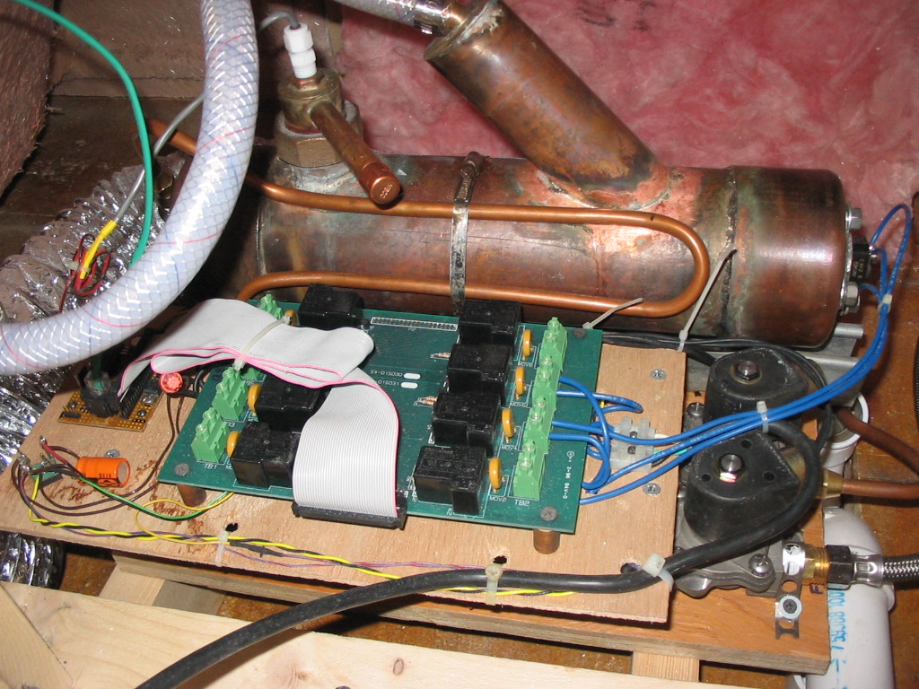
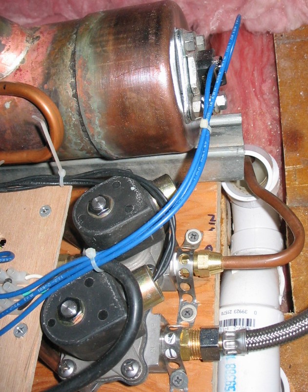
The tank is a 4" copper pipe with end caps. It is silver soldered to withstand heat. The replacable 3000W heating element extends inward through one end of the tank. Stainless bolts are used. The relay card is a pre-existing unit that I had in my collection. The 220/24V transformer, solid state relay, cooling fan are below the relay card. The "U" shaped 1/4" flexible copper tubing alongside the tank is for preheating the incoming water so that it doesn't squelch the steam when the inlet water valve opens.
Click on photo to display full size version.
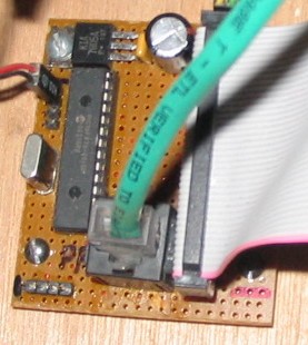
The microcontroller board is really quite simple. The water level switch comes on on the black/red wires. Other connectors exist for the 5V cooling fan, solid state relay, and thermal sensor. Control panel comes in on the green cable and RJ-45 connector. The relay board is connected via flat ribbon cable. The ICSP PIC programming port is at the lower left.
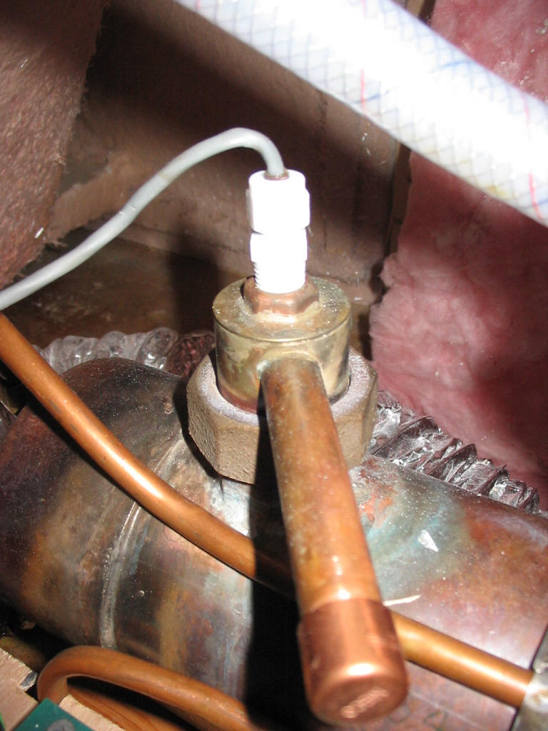
The tank level switch is is mounted in an assembly that can be removed. The capped copper pipe in the forground will eventually get an over-pressure safety valve.
Click on photo to display full size version.
The two water valves are for inlet and drain. They have a 5/8" orifice opening, which is really much larger than necessary for the water inlet, which is significantly throttled down by a petcock in the water supply. The drain valve (at bottom of the photo) should be capable of withstanding water that is 80-100C. It drains by gravity (into the white PVC in the photo) so the 5/8" orifice opening is helpful. The 3000W heating element connection is seen at the righthand end of the copper tank.
Click on photo to display full size version.
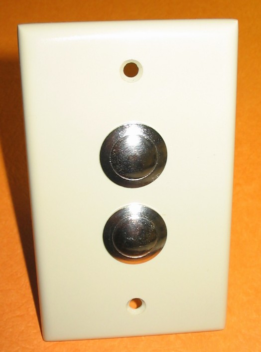
The control panel is simply two push button switches mounted on a standard blank switch plate.
Click on photo to display full size version.
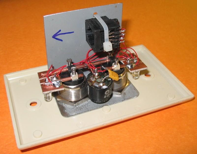
There are two bright white LEDs that are visible through the ivory colored switch plate, as well as an RJ-45 jack and piezo beeper mounted behind the panel.
Click on photo to display full size version.
Operation
Normal operation
- Turn power on. LED's will flash rapidly for one second during initilization.
- Press Button 1 to start heavy steam; Button 2 to start light steam.
- LED flashes to show which mode is selected, and present status...
- SLOW - filling & preheating (approximately 10 minutes) after which generator beeps five times to signal it's ready.
- SOLID - soak mode (25 minutes). During this time buttons may be pressed to choose heavy or light steam.
- FAST - warn period (2 minutes). Beeps every minute, either press a button to continue, or ignore it and the generator will stop and drain.
- SLOW - draining and rinsing (waits until temperature is lower than 65C.)
- Press and hold either button for two seconds to force early stop, drain, and rinse.
- Don't turn power off until LEDs are off.
Reset
- Press and hold both buttons for five seconds to reset generator (simply stops where it is, no drain, etc.)
Errors
- Errors cause an immediate stop…no draining. Count the number of quick flashes:
- not drained at start
- not filled within time limit during initial fill cycle
- not filled within time limit during rinse cycle
- not periodically refilling while boiling
- over temperature (105C or greater) detected during preheat or soak cycles
- under temperature (90C or less) detected after preheat cycle
Technical Reference
HARDWARE
- As with any several-thousand watt heating element, care must be given to safe design and installation!
SOFTWARE
- Control is handled by a large state machine.
CORRECTIONS OR UPDATES
- v1.0 - first release