Modified 12/28/09
This schematic and source code are intended for demonstration purposes only. They are offered "as-is". Use at your own risk.This circuit must not be connected to live cables!
Code and circuits (and more) are here.
Introduction
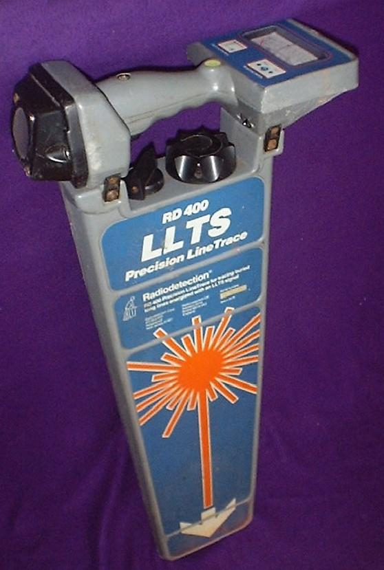
I obtained an early vintage Radiodetection® RD400 "LLTS" Precision Line Trace unit for a very low price through eBay. The RD400 is the receiver portion of a transmitter/receiver pair that comprise an underground cable locator system. Because the matching transmitter was not available (hence the low price,) I had to design one that matched the two audio frequencies detected by the receiver.
Click on photo to display full size version.
"LLTS" means Long Line Tracing System. Used with original transmitter, this unit was said to be capable of tracing signals in cables up to 45 miles. One of the most useful home-based applications of an underground locator is for locating breaks in the perimeter cable of underground dog fences!
Features
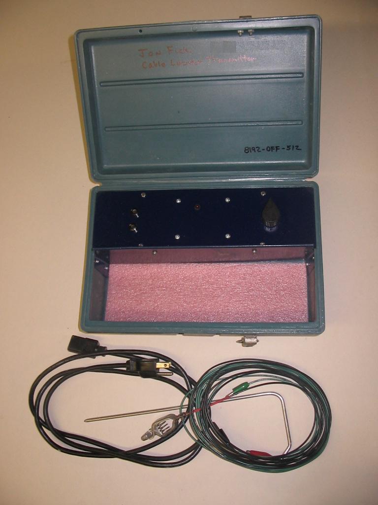
This transmitter is a simple design. The only control is a three-position rotary switch or center-off DPDT toggle switch. The transmitter is housed in a case that contains the 120VAC power cable, test cables, ground rod, and current clamp (not shown.)
Click on photo to display full size version.
Specifications
- Power: 8-35VDC such as from a wall adapter for 120VAC 60Hz
- Output: 512Hz or 8192Hz modified sine wave, 50-80VAC
Operation
Switch the unit on to either 512Hz or 8192Hz. The LED flashes slowly (1Hz rate) if 512Hz is selected; fast (16Hz rate) if 8192Hz is selected.
The receiver detects the electromagnetic field generated by the transmitters signal in the underground cable. Because magnetics are involved, and because magnetic fields are induced by current flow, and because current cannot flow without a complete circuit, it requires that whatever means of connection to the underground cable is used, signal current must be caused to flow in the cable being detected. Therefore, some thought may be necessary to get a useful signal into an underground cable.
- Direct connection...connect one output lead to the non-energized underground cable being located. Connect the other output lead to a ground rod. Transmitter signal current flows via capacitive coupling from the underground into the surrounding ground. The return path for the current is through the ground rod.
- Inductive connection...a current clamp will induce a current in the cable if it's connected in some way that will allow signal current to flow...this will not work if the ends of the cable are disconnected because there is no return path. For instance, a buried pipe in contact with the soil may have enough current flow from one end of the pipe to the other to be detected by the receiver if the current clamp is somewhere along the path.
Once connected, use the receiver, set to the same frequency, per the instructions printed on it's side, to locate the signal along the cable path.
Helpful application notes may be found in the Library section of the Radiodetection website.
Technical Reference
HARDWARE
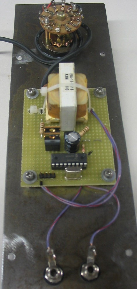
- The Triad F-132P transformer is a 60Hz power transformer having a 120V winding and two 7.5V 100mA windings. I chose this transformer because I had it on the shelf. Although designed for 60Hz, it does well enough to pass 512Hz and 8192Hz energy for this application.
- The MOSFET transistors
are rated for 40amps and are fairly robust. However,
the gates are quite susceptable to damage from over-voltage transients, so
careful wiring practice is important. That is, ensure that the MOSFET
sources are well grounded at one point, and make that point the common
ground for the remaining circuitry.
Click on photo to display full size version.
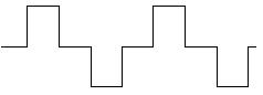
- The output is a "modified sine wave" as illustrated below.
This is an approximation of a sine wave that is created by introducing a delay
after changing the state of one PIC output before changing the other output to
the opposite state. This ensures that there is no overlap and resulting
shoot-thru current that could damage the MOSFETs.
A modified sine wave should also reduce, at least to some extent,
the harmonics injected into the cable under test.
- I'm sure some analog engineers who are good with transformer coupling
will think the output stage of this
transmitter is not very well designed, but it does work. (I'm interested
in any suggestions for improvement!) The two MOSFET transistors switch
the output transformer in a push-pull mode. Excessive ringing is controlled
by the diodes and 10Ω resistors on the two primary windings,
and the 0.0015uF capacitor across the secondary winding.
- If the output is connected to a live 120VAC or 240VAC circuit, the transformer will generate 7.5V in each winding which will backfeed into the circuitry. Although unverified, I'd expect the diodes to half-wave rectify and heat things up. Therefore, don't connect this generator to a live cable!
- If live cables are a possibility, a better anti-ringing scheme than diodes might be capacitors. Alternatively, the two windings could be fused. Probably the best solution is to wire a series choke to one of the output jacks, electrically sized as a high-pass filter to limit 60Hz current to acceptable levels but still pass adequate 512Hz and 8192Hz current.
- Another method to avoid direct connection to a live cable is to inductively couple the transmitter signal to the cable using a suitable current clamp. My transmitter circuitry seems to adequately drive a surplus current clamp. Using a current clamp has caveats; refer to the theory and links above.
- A four-pin programming port is provided for convenient in-circuit programming, something I now do for all my projects.
- A 9VDC 750mA wall adapter is used to power this unit. This input voltage is not critical for the 78L05 voltage regulator, but I don't believe the voltage should go too much higher at the center-tap of the transformer due to the ratings of the transformer. The input power switch selects between the AC wall adapter supply and six D-cells. The unit draws approximately 100mA.
- A cleaner injected signal (without harmonics) could be obtained if this generator was used to phase lock a function generator chip (such as the Maxim MAX038) whose output would then be (audio) amplified and fed into the underground cable.
SOFTWARE
- This is a "brute-force" design whereby the two output pins are controlled by software loops that were precisely designed. That is, the cycle counts of the delay_us and delay_cycles instructions were "tuned" so that the exact frequencies would be generated. There is nothing elegant about this coding!
- The maximum crystal frequency (20MHz) was chosen so that each cycle would be the shortest available (200pS). At this clock cycle, 512Hz is easy to generate; 8192 is not quite as exact but close enough. The receiver is quite sensitive...a cycle or two high or low is enough to be out of the receiver's range.
- Future: it would be nice to have a "calibrate" scheme whereby a button would allow the user to step through a sequence and precisely tune the transmitter to the recievers frequencies, storing the resulting cycle delays in EEPROM. However, even with assembly language coding, the minimum dynamic (at runtime) steps are three cycles, and this is too coarse to precisely hit 8192Hz.
CORRECTIONS OR UPDATES
- v1.0 - first release